Pipe Marking Guide

Identification Colors

This is a comprehensive guide on identification pipe marking colours for the content of piping systems according to ISO 14726 standard, including single and multi-colour combinations for ships and marine industry.

A-SPE pipe markers are made to the latest standards and regulations required by customers and can be designed to comply with one of the following norms: ISO 14726:2008, BS-1710 / BS-4800, ANSI/ASME A13-1, TRGS-201, NBR 6493 or any other marine and industrial standard. The use of colour in the identification of pipes can be based on the following colour charts: RAL, Pantone or Munsell.

red pipeline with red marker on ship

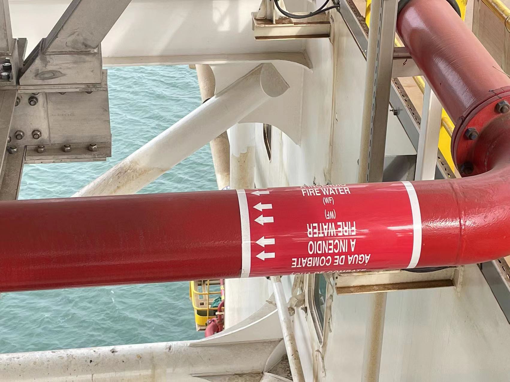
Apart from specific colour-coding which identifies a pipe medium and possible hazards related to that substance, pipe labels can be equipped with additional information, including flow direction, secondary language, system code, system description, line numbers or QR codes. The font type and the letter height are another requirements, next to the colours, that need to be taken into account, so that the written identification of the content is clearly visible and legible. The height of text characters should correspond to the appropriate pipe outside diameter. The recommended pipe marker dimensions for most popular nominal pipe sizes can be further found in our Pipe Marking Dimension Table below.

Basic Identification Tapes
(acc. to ISO 14726:2008)

black ral 9005
Description
Waste media
Order code
SC40
ISSA
47.521.40
IMPA
33.2140
blue ral 5015
Description
Fresh water
Order code
SC41
ISSA
47.521.41
IMPA
33.2141
brown ral 8001
Description
Fuel
Order code
SC42
ISSA
 47.521.42
IMPA
33.2142
green ral 6018
Description
Sea Water
Order code
SC43
ISSA
47.521.43
IMPA
33.2143
grey ral 7001
Description
Non-flammable Gases
Order code
SC44
ISSA
47.521.44
IMPA
33.2144
maroon ral 8015
Description
Air and sounding pipes
Order code
SC45
ISSA
47.521.45
IMPA
33.2145
orange ral 2003
Description
Oil other than fuels
Order code
SC46
ISSA
47.521.46
IMPA
33.2146
silver ral 9006
Description
Steam
Order code
SC47
ISSA
47.521.47
IMPA
33.2147
red ral 3000
Description
Fire fighting
Order code
SC48
ISSA
47.521.48
IMPA
33.2148
violet ral 4001
Description
Acids & Alkalis
Order code
SC49
ISSA
47.521.49
IMPA
33.2149
white ral 9010
Description
Air in ventilation systems
Order code
SC50
ISSA
47.521.50
IMPA
33.2150
yellow ral 1021
Description
Flammable gases
Order code
SC51
ISSA
47.521.51
IMPA
33.2151
Description
Flow direction marking
Order code
SC30
ISSA
47.521.30
IMPA
33.2130

Multi-Colour Permutations (acc. to ISO 14726:2008)

Description
Waste media
Order code
MC40
Description
Black water
Order code
MC40-41
Description
Waste oil / Used oil
Order code
MC40-42
Description
Bilge water
Order code
MC40-43
Description
Exhaust gas
Order code
MC40-44
Description
Grey water
Order code
MC40-50
Description
Sewage -  contaminated
Order code
MC40-51
Description
Fresh water
Order code
MC41
Description
Fresh water, sanitary
Order code
MC41-42
Description
Potable water
Order code
MC41-43
Description
Distillate
Order code
MC41-44
Description
Gas turbine wash water
Order code
MC41-46
Description
Feed water
Order code
MC41-47
Description
Cooling fresh water
Order code
MC41-49
Description
Chilled water
Order code
MC41-50
Description
Condensate
Order code
MC41-51
Description
Fuel
Order code
MC42
Description
Heavy fuel oil (HFO)
Order code
MC42-40
Description
Aviation fuel
Order code
MC42-41
Description
Biological fuel
Order code
MC42-49
Description
Gas-turbine fuel
Order code
MC42-50
Description
Marine diesel fuel (MDO)
Order code
MC42-51
Description
Sea water
Order code
MC43
Description
Decontamination water
Order code
MC43-41
Description
Sea water, sanitary
Order code
MC43-42
Description
Ballast water
Order code
MC43-49
Description
Cooling sea water
Order code
MC43-51
Description
Non-Flammable gases
Order code
MC44
Description
Oxygen
Order code
MC44-41
Description
Inert gas
Order code
MC44-42
Description
Nitrogen
Order code
MC44-43
Description
Refrigerant
Order code
MC44-45
Description
Compressed air LP (low pressure)
Order code
MC44-46
Description
Compressed air HP (high pressure)
Order code
MC44-48
Description
Control air / Regulating air
Order code
MC44-49
Description
Breathing air*
Order code
MC44-50
Description
Breathing gas*
Order code
MC44-51
Description
Masses
Order code
MC45
Description
Waste media
Order code
MC45-40
Description
Fresh water
Order code
MC45-41
Description
Fuel
Order code
MC45-42
Description
Sea water
Order code
MC45-43
Description
Non-flammable gases
Order code
MC45-44
Description
Oil other than fuels
Order code
MC45-46
Description
Steam
Order code
MC45-47
Description
Fire fighting
Order code
MC45-48
Description
Acids, alkalis
Order code
MC45-49
Description
Ventilation system
Order code
MC45-51
Description
Flammable gases
Order code
MC43-51
Description
Oil other than fuels
Order code
MC46
Description
Thermal fluid
Order code
MC46-41
Description
Lubricaition oil for gas turbines
Order code
MC46-43
Description
Hydraulic fluid
Order code
MC46-44
Description
Lubricaition oil for steam turbines
Order code
MC46-47
Description
Lubricaition oil for gears
Order code
MC46-49
Description
Lubricaition oil for int. combustion engines
Order code
MC46-51
Description
Steam
Order code
MC47
Description
Steam for heating purposes
Order code
MC47-40
Description
Driving steam
Order code
MC47-43
Description
Exhaust steam
Order code
MC47-50
Description
Exhaust steam
Order code
MC47-51
Description
Fire fighting / Fire protection
Order code
MC48
Description
Fire-fighting water
Order code
MC48-43
Description
Fire-fighting gas
Order code
MC48-44
Description
Sprinkler water
Order code
MC48-46
Description
Spray water
Order code
MC48-49
Description
Fire-fighting powder
Order code
MC48-50
Description
Fire-fighting foam
Order code
MC48-51
Description
Acids & Alkalis
Order code
MC49
Description
Air in ventilation systems
Order code
MC50
Description
Discharge air
Order code
MC50-40
Description
Mechanical supply air - cold
Order code
MC50-41
Description
Natural exhaust air
Order code
MC50-42
Description
Atmospheric air
Order code
MC50-43
Description
Mechanical exhaust air
Order code
MC50-44
Description
Decontaminated supply air
Order code
MC50-45
Description
Mechanical recirculated air
Order code
MC50-46
Description
Mechanical supply air - warm
Order code
MC50-47
Description
Smoke clearance
Order code
MC50-48
Description
Conditioned supply air
Order code
MC50-49
Description
Natural supply air
Order code
MC50-51
Description
Flammable gases
Order code
MC51
Description
Acetylene
Order code
MC51-41
Description
Driving steam
Order code
MC51-44
Description
Liquid gas
Order code
MC51-49

Design and Dimensions

The pipe labelling should go around the entire circumference of the pipe and should be applied to the exterior of insulated and un-insulated pipelines.

The below table shows recommended pipe marker dimensions for most popular nominal pipe sizes. Each marker length comes with suitable font and arrow sizes. The sizes include a minimum 30mm overlap, however they do not include any additional pipe coatings like insulation etc.

Information about insulation thickness or other coatings should be provided with other details necessary for the quotation.
Nominal Pipe Diameter
DN 15
Pipe Diameter
 1/2"
Marker lenght
100 mm
Letter height
6,5 mm
Arrow hieght
16 mm
Nominal Pipe Diameter
DN 20
Pipe Diameter
 3/4"
Marker lenght
115 mm
Letter height
13 mm
Arrow hieght
16 mm
Nominal Pipe Diameter
DN 25
Pipe Diameter
 1"
Marker lenght
135 mm
Letter height
13 mm
Arrow hieght
16 mm
Nominal Pipe Diameter
DN 32
Pipe Diameter
 1,25"
Marker lenght
165 mm
Letter height
19 mm
Arrow hieght
19 mm
Nominal Pipe Diameter
DN 40
Pipe Diameter
1,50"
Marker lenght
190 mm
Letter height
19 mm
Arrow hieght
19 mm
Nominal Pipe Diameter
DN 50
Pipe Diameter
 2"
Marker lenght
230 mm
Letter height
19 mm
Arrow hieght
19 mm
Nominal Pipe Diameter
DN 65
Pipe Diameter
2,5"
Marker lenght
270 mm
Letter height
32 mm
Arrow hieght
32 mm
Nominal Pipe Diameter
DN 80
Pipe Diameter
3"
Marker lenght
320 mm
Letter height
32 mm
Arrow hieght
32 mm
Nominal Pipe Diameter
DN 100
Pipe Diameter
4"
Length of the marker
395 mm
Letter height
32 mm
Arrow hieght
32 mm
Nominal Pipe Diameter
DN 150
Pipe Diameter
6"
Marker lenght
580 mm
Letter height
32 mm
Arrow hieght
32 mm
Nominal Pipe Diameter
DN 200
Pipe Diameter
8"
Marker lenght
760 mm
Letter height
32 mm
Arrow hieght
32 mm
Nominal Pipe Diameter
DN 250
Pipe Diameter
10"
Marker lenght
945 mm
Letter height
32 mm
Arrow hieght
32 mm
Nominal Pipe Diameter
DN 300
Pipe Diameter
 12"
Marker lenght
1120 mm
Letter height
32 mm
Arrow hieght
32 mm
Nominal Pipe Diameter
DN 350
Pipe Diameter
14"
Marker lenght
1230 mm
Letter height
32 mm
Arrow hieght
32 mm
Nominal Pipe Diameter
DN 400
Pipe Diameter
16"
Marker lenght
1400 mm
Letter height
32 mm
Arrow hieght
32 mm
Nominal Pipe Diameter
DN 450
Pipe Diameter
18"
Marker lenght
1580 mm
Letter height
32 mm
Arrow hieght
32 mm
Nominal Pipe Diameter
DN 500
Pipe Diameter
20"
Marker lenght
1750 mm
Letter height
32 mm
Arrow hieght
32 mm
Nominal Pipe Diameter
DN 600
Pipe Diameter
24"
Marker lenght
2100 mm
Letter height
32 mm
Arrow hieght
32 mm
Nominal Pipe Diameter
DN 700
Pipe Diameter
28"
Marker lenght
2400 mm
Letter height
32 mm
Arrow hieght
32 mm
Nominal Pipe Diameter
DN 750
Pipe Diameter
30"
Marker lenght
2550 mm
Letter height
32 mm
Arrow hieght
32 mm
Nominal Pipe Diameter
DN 15
Pipe Diameter
36"
Marker lenght
3050 mm
Letter height
32 mm
Arrow hieght
32 mm
Nominal Pipe Diameter
DN 1100
Pipe Diameter
44"
Marker lenght
3700 mm
Letter height
32 mm
Arrow hieght
32 mm
Nominal Pipe Diameter
DN 1200
Pipe Diameter
48"
Marker lenght
4050 mm
Letter height
32 mm
Arrow hieght
32 mm

Installation Tips

Important: During application the tape should overlap 3-4 cm

Properly installed markers serve for many years and improve the level of occupational safety, helping to reduce the amount of downtime and accidents. The positioning of pipe marking must make it possible for personnel to identify the pipeline from the point of normal approach. 

pipeline schema where to use pipe marking

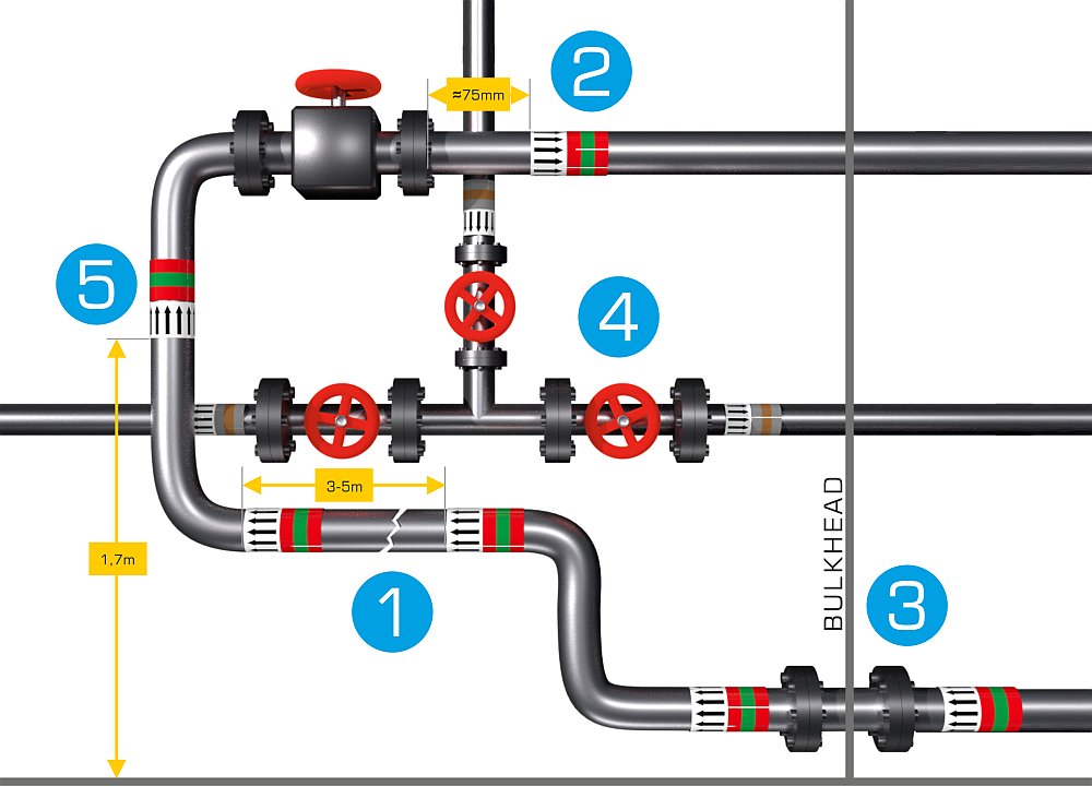
According to the ISO 14726:2008 regulation, the following points should be considered during the installation of pipe markers:

  1. Markers should be installed within a 3-5m distance between each marking point on a horizontal and vertical pipeline. Branched pipes or close proximity to pipes carrying different media may require a more frequent marking.
  2. In case of valves, markers should be installed at a distance of approx. 75mm from the corresponding flange.
  3. Markers should be mounted at all penetration points in walls, bulkheads or decks.
  4. Markers should be installed on each side of the pipe branch.
  5. In case of a vertical piping system, markers should be applied at a height of approx. 170cm to ensure good visibility.

The exact estimation of the quantity of markers and installation points is determined at the stage of material preparation. A-SPE specialists can offer you professional advice based on the provided pipeline scheme and detailed specifications.